
As a group we believe that if we had the oppurtunity to do this again between us we would not do anything different, we set tasks and the four of us would have weekly meetings or even more and by the next meeting the work that had been set previously would be completed. The team had great communication and this was our best strength and what had seperated us from the other groups.
The commitment the team had showed really shone through when coming together with people we hardly knew to meeting and discussing work on a daily basis.
Choosing the design was the hardest challenge we had to choose a design that would be different and unique to stand out from the rest of the designs. the design was simple so it did not need training or instructions to set up, it is self-explantory. The design the team had chosen was versatile and easily portable.
Thursday, 29 April 2010
finance
The cost for 7 meters worth of aluminum bars came to a total of £779.86
The cost of the 3.1 meter I-Beam came to £354.14
The cost of the bottle jack was £20 x 4 = £80
The labourers cost for welding came to £120
The total costing came to £1334 ~ £1400
As this is a disaster saving tender we do not intend to make any profit on this there is no price on the lives of people. All costing has been taken into consideration and as nearly all of it will come pre-made there is no extra machining necessary. The aluminum bars came from the Aluminum Warehouse, the bars they supplied were what we needed.
The I-Beam was a great find I found an online company funnily enough called Online Metals and I was able to give them my dimensions and they gave me a quote instantly. The price they had quoted me was reasonable and as the financial officer I had set an initial budget of around £1500 so the crane complete cost was pleasing.
The design allows the toes' on each of the legs to accomodate to most jacks. So this would save on costing and would be able to help the disaster more efficiently as in it would mean the government or whoever the buyer would be would be able to buy bulk at cheaper prices.
Monday, 26 April 2010
Contractor SWOT analysis
The following is a SWOT analysis of the group, not the product. Hector Vela Garza has not been included as he has not been a part of the project:
Strengths:
1. Structure. The group assigned responsibilities and roles to each individual at an early stage. These responsibilities have allowed each member to act independently of the group, seeking advice when needed; as well as delegating tasks to other group members where appropriate.
2. Flexibility. The flexibility of all group members to act 'out of role' has been a significant success story. Combining this with the weekly group meeting has kept the structure of the group in tact and the project on track. The willingness of all group members to adapt ideas and take on board constructive criticism has seen many changes occur from the original design; all significantly improving the completed product.
3. Commitment. The group has remained committed to the project from the start. Any other responsibilities have been kept way from group time; with the use of a blog greatly enhancing the way the group monitors and adapts to changes; especially short notice ones.
Weaknesses.
1. Meeting group deadlines. All individuals have had to make short term changes to the timescales set in order to achieve a better result. These short notice changes have been handled well but could have resulted in friction occurring. Fortunately the group has not suffered from any ill feeling with any issues or opposing opinions addressed immediately. The use of the blog, email and text messaging has kept all others in the loop and helped prevent problems develop.
2. Sub teams. The use of sub teams has helped the group achieve results quickly; but has also become 'the norm' with respect to operating procedures. If the project was to be completed over a longer timescale then a change of sub team composition would enhance group cohesion.
Opportunities.
1. Blogging. The use of a blog was a first for many of the group, however this method of developing a product/plan has proved to be most effective. It is definitely a valuable tool that the group plan to take the opportunity to use in the future.
2. Planning criteria. If the group were to undertake a project like this again it would be a useful opportunity to develop a number of different solutions; and be in a stronger position to pick the most suitable design for further production.
Threats
1. Limitations. The lack of a 'shared area' of online space to store designs and documentation has hindered the creation of the product. If any such area was to be made available then the flexibility of the group, to work without a missing member, would allow production to continue. At times the group has been hindered because an individual has the documentation/design that the rest of the group needs, in order to develop it further. The blog is a useful tool but would greatly benefit from adding this feature.
Friday, 23 April 2010


Buckling
In engineering, buckling is a failure mode characterized by a sudden failure of a structural member subjected to high compressive stresses, where the actual compressive stress at the point of failure is less than the ultimate compressive stresses that the material is capable of withstanding. This mode of failure is also described as failure due to elastic instability. Mathematical analysis of buckling makes use of an axial load eccentricity that introduces a moment, which does not form part of the primary forces to which the member is subjected.


Corrosion Prevention
• Materials - Noble or close on series
• Where dissimilar metals in contact, more anodic metal should constitute larger surface area
• Protective coatings
• Environment - pH, de-aeration
• Cathodic Protection - Sacrificial anode
• Detail design - eg, avoidance of crevices, draining
• Vehicles: ventilation to minimise moisture
• Where dissimilar metals in contact, more anodic metal should constitute larger surface area
• Protective coatings
• Environment - pH, de-aeration
• Cathodic Protection - Sacrificial anode
• Detail design - eg, avoidance of crevices, draining
• Vehicles: ventilation to minimise moisture
Consequences of Corrosion
• General thinning (wastage)
1. Material corroded fairly uniformly over wide area, and where the flaky and porous corrosion products no barrier to further corrosion
• Passive film formation (beneficial)
1. Corrosion products form durable & impervious barrier which slows down / halts more corrosion
• Oxidation (mainly high temperature ‘dry’)
1. Consequence: scale formation which causes eg blockages in pipe work
• Pitting
1. Material selectively attacked to form spherical pits
• Cracking
1. Selective attack leads to formation of deep, sharp-fronted cracks
Corrosion
• Deterioration of materials through chemical or electro-chemical interaction with environment
• Attack on metals by agents such as polluted air; sea water (sodium chloride), leading to formation of rust
• Most corrosion ‘wet’
• Lecture approach mainly not via chemical reactions
1. Not a unifying theme for explanations of different corrosion modes
2. Personal sensitivities
• Two different metals electrically in contact immersed in electrolyte
1. Creates galvanic couple where more active metal corrodes (anode) at accelerated rate and more noble metal (cathode) corrodes at a retarded rate (or zero)
• Electrical cells also created by eg:
1. Air bubbles / water droplets
2. Differential stresses in same metal causing local galvanic couple (stress corrosion cracking)
Corrosion
Corrosion is the disintegration of an engineered material into its constituent atoms due to chemical reactions with its surroundings. In the most common use of the word, this means electrochemical oxidation of metals in reaction with an oxidant such as oxygen. Formation of an oxide of iron due to oxidation of the iron atoms in solid solution is a well-known example of electrochemical corrosion, commonly known as rusting. This type of damage typically produces oxide(s) and/or salt(s) of the original metal. Corrosion can also refer to other materials than metals, such as ceramics or polymers, although in this context, the term degradation is more common.
In other words, corrosion is the wearing away of metals due to a chemical reaction.
Many structural alloys corrode merely from exposure to moisture in the air, but the process can be strongly affected by exposure to certain substances (see below). Corrosion can be concentrated locally to form a pit or crack, or it can extend across a wide area more or less uniformly corroding the surface. Because corrosion is a diffusion controlled process, it occurs on exposed surfaces. As a result, methods to reduce the activity of the exposed surface, such as passivation and chromate-conversion, can increase a material's corrosion resistance. However, some corrosion mechanisms are less visible and less predictable.
Brittle - Ductile - Creep Example

BOILER SUPERHEATER FAILURE EXAMPLE
from left to right, the first one will be Ductile Failure, the one in the middle will be Brittle Failure, and the one on the right will be Creep Failure.
Preventing Creep Failures
• Design stresses and temperatures based on creep test data
• Selection of materials
1. Good: eg, 1% or more chromium; 0.5% molybdenum steel
• Minimisation of thermal expansion stresses
• Selection of materials
1. Good: eg, 1% or more chromium; 0.5% molybdenum steel
• Minimisation of thermal expansion stresses
Creep Failures
• Excessive deformation
1. Gas turbine blades
2. Lead on roofs
3. Suspension bridge cables
• Rupture
1. Trans-granular: deformation
2. Inter-granular: little / no deformation where longer lives; higher temperatures
• Pre-stressed concrete (eg, in fires)
1. Pre-stress eliminated
• Prolonged overheating
1. Just 50ºC above specification: 90% reduction in life
2. 11 years at 500ºC; one hour at 700ºC

Creep
Creep is the tendency of a solid material to slowly move or deform permanently under the influence of stresses. It occurs as a result of long term exposure to high levels of stress that are below the yield strength of the material. Creep is more severe in materials that are subjected to heat for long periods, and near the melting point. Creep always increases with temperature.
The rate of this deformation is a function of the material properties, exposure time, exposure temperature and the applied structural load. Depending on the magnitude of the applied stress and its duration, the deformation may become so large that a component can no longer perform its function — for example creep of a turbine blade will cause the blade to contact the casing, resulting in the failure of the blade. Creep is usually of concern to engineers and metallurgists when evaluating components that operate under high stresses or high temperatures. Creep is a deformation mechanism that may or may not constitute a failure mode. Moderate creep in concrete is sometimes welcomed because it relieves tensile stresses that might otherwise lead to cracking.
Unlike brittle fracture, creep deformation does not occur suddenly upon the application of stress. Instead, strain accumulates as a result of long-term stress. Creep deformation is "time-dependent" deformation.
The temperature range in which creep deformation may occur differs in various materials. For example, Tungsten requires a temperature in the thousands of degrees before creep deformation can occur while ice formations will creep in freezing temperatures.[1] As a rule of thumb, the effects of creep deformation generally become noticeable at approximately 30% of the melting point for metals and 40–50% of melting point for ceramics. Virtually any material will creep upon approaching its melting temperature. Since the minimum temperature is relative to melting point, creep can be seen at relatively low temperatures for some materials. Plastics and low-melting-temperature metals, including many solders, creep at room temperature as can be seen markedly in old lead hot-water pipes. Planetary ice is often at a high temperature relative to its melting point, and creeps.
Creep deformation is important not only in systems where high temperatures are endured such as nuclear power plants, jet engines and heat exchangers, but also in the design of many everyday objects. For example, metal paper clips are stronger than plastic ones because plastics creep at room temperatures. Aging glass windows are often erroneously used as an example of this phenomenon: measurable creep would only occur at temperatures above the glass transition temperature around 500 °C (900 °F). While glass does exhibit creep under the right conditions, apparent sagging in old windows may instead be a consequence of obsolete manufacturing processes, such as that used to create crown glass, which resulted in inconsistent thickness.[2][3]
An example of an application involving creep deformation is the design of tungsten light bulb filaments. Sagging of the filament coil between its supports increases with time due to creep deformation caused by the weight of the filament itself. If too much deformation occurs, the adjacent turns of the coil touch one another, causing an electrical short and local overheating, which quickly leads to failure of the filament. The coil geometry and supports are therefore designed to limit the stresses caused by the weight of the filament, and a special tungsten alloy with small amounts of oxygen trapped in the crystallite grain boundaries is used to slow the rate of coble creep.
In steam turbine power plants, pipes carry steam at high temperatures (566 °C or 1050 °F) and pressures (above 24.1 MPa or 3500 psi). In jet engines, temperatures can reach up to 1400 °C (2550 °F) and initiate creep deformation in even advanced-coated turbine blades. Hence, it is crucial for correct functionality to understand the creep deformation behavior of materials.
Preventing Fatigue Failures
• Reduce magnitude of fluctuating stresses and of stress concentrations
• Beware ‘unexpected’ bending stresses
• Realistic testing (measure service load history)
• Standard cumulative damage predictions (Miner’s Law) inaccurate
• In general hardening the material raises the threshold (see above)
• Surface hardening techniques
o Carburising
o Nitriding
o Shot peening
• Introduce residual compressive stresses
• Changing the material
• Solutions difficult because of the lack of predictability
• ‘Scatter’ in lab tests great
• In service, load histories may vary dramatically:
1. Motor vehicles
2. Cranes
3. Pressure vessels
• Even greater ‘scatter’
• Non-destructive testing:
1. Oil and chalk (dye penetrants)
2. Magnetic particle
3. Ultrasonics
4. Radiography
• Interpretation?
1. Note distinction: is there a crack? How deep is it?


Fatigue
• Slow development of cracks in components:
1. Repeated or fluctuating stresses (pre-requisite)
2. Failure much lower than σy of material
3. Note fallacy of ‘safety factors’
4. Real ‘safety factor’ (margin of spare capacity) - must be based on all plausible modes of failure
• How fatigue cracks grow
1. Initiation
2. Propagation
3. Each load cycle produces a small striation
4. When the crack stops a beach mark is generated
5. Fracture (brittle or ductile) of residual material
Characteristics of fatigue
• In metals and alloys, the process starts with dislocation movements, eventually forming persistent slip bands that nucleate short cracks.
• Fatigue is a stochastic process, often showing considerable scatter even in controlled environments.
• The greater the applied stress range, the shorter the life.
• Fatigue life scatter tends to increase for longer fatigue lives.
• Damage is cumulative. Materials do not recover when rested.
• Fatigue life is influenced by a variety of factors, such as temperature, surface finish, microstructure, presence of oxidizing or inert chemicals, residual stresses, contact (fretting), etc.
• Some materials (e.g., some steel and titanium alloys) exhibit a theoretical fatigue limit below which continued loading does not lead to failure.
• In recent years, researchers (see, for example, the work of Bathias, Murakami, and Stanzl-Tschegg) have found that failures occur below the theoretical fatigue limit at very high fatigue lives (109 to 1010 cycles). An ultrasonic resonance technique is used in these experiments with frequencies around 10–20 kHz.
• High cycle fatigue strength (about 103 to 108 cycles) can be described by stress-based parameters. A load-controlled servo-hydraulic test rig is commonly used in these tests, with frequencies of around 20–50 Hz. Other sorts of machines—like resonant magnetic machines—can also be used, achieving frequencies up to 250 Hz.
• Low cycle fatigue (typically less than 103 cycles) is associated with widespread plasticity in metals; thus, a strain-based parameter should be used for fatigue life prediction in metals and alloys. Testing is conducted with constant strain amplitudes typically at 0.01–5 Hz.

Errors leading to failure
Errors leading to failure can occur during
• Design
• Material manufacture and heat treatment
• Fabrication, machining and assembly
• Installation
• Operation
• Demolition or scrapping
• Design
• Material manufacture and heat treatment
• Fabrication, machining and assembly
• Installation
• Operation
• Demolition or scrapping
Brittle Fractures

In brittle fracture, no apparent plastic deformation takes place before fracture. In brittle crystalline materials, fracture can occur by cleavage as the result of tensile stress acting normal to crystallographic planes with low bonding (cleavage planes). In amorphous solids, by contrast, the lack of a crystalline structure results in a conchoidal fracture, with cracks proceeding normal to the applied tension.
Ductile Fractures

In ductile fracture, extensive plastic deformation takes place before fracture. Many ductile metals, especially materials with high purity, can sustain very large deformation of 50–100% or more strain before fracture under favorable loading condition and environmental condition. The strain at which the fracture happens is controlled by the purity of the materials. At room temperature, pure iron can undergo deformation up to 100% strain before breaking, while cast iron or high-carbon steels can barely sustain 3% of strain.[citation needed].
Because ductile rupture involves a high degree of plastic deformation, the fracture behavior of a propagating crack as modeled above changes fundamentally. Some of the energy from stress concentrations at the crack tips is dissipated by plastic deformation before the crack actually propagates.
The basic steps sample of smallest cross-sectional area), void formation, void coalescence (also known as crack formation), crack propagation, and failure, often resulting in a cup-and-cone shaped failure surface.
Thursday, 22 April 2010
eulers theroem
 finally worked out the stress that the bars can take using aluminium alloy with young's modulus of 70GPa and found that our bars would withstand the forces applied, result! now just have to find a supplier.


Final design of the leg

This is a Solidworks drawing of the leg we are going to be using, with dimensions.
Final design film of assembly
This is a video showing the crane gantry being disassembled and reassembled using the final design of the components.
Group meeting
On Monday 26th April the group will have a presentation meeting in the library at 1230hrs. All individuals are to arrive with the material they would like to include in the group presentation (on Wednesday 28th Apr). This information should have already been included as a blog entry prior to the meeting.
A further practice session is also planned for Tuesday 27th Apr.
A further practice session is also planned for Tuesday 27th Apr.
Hoists.

The group has realised that the design is perfectly capable of utilising a hoist system; should it be needed. Therefore the following hoists would be recommended to any potential customers. There are quite literally hundreds available but these simple effective designs are a good example of what could be utilised; with the principle of 'any safe tool' will do in a disaster situation:
1. Hand Chain Hoists & Chain Block
Designed for long life with minimum maintenance, the BUDGIT USA family of hand chain hoist products have outstanding features, including: lightweight, tight headroom, overload devices as standard, and easy operation. The 1/4 through 6-ton Budgit hoist models are all of the same basic construction and consist of a cast aluminum frame which houses an automatic load brake, spur gear reduction and load sprocket with chain guide. The suspension hooks swivel 360 degrees. All of the chain block models that Budgit makes are made in the USA and will meet all your needs for commercial and industrial use
SWL 2 Ton [$1,075.84]
http://www.hoistsdirect.com/
2. Budgit Electric Chain Hoist Series
New heavy-duty positive acting AC disc motor brake. This long lasting brake has an easy 1-step adjustment.
New upper suspension design threads through the upper frame and is locked in place at the top of the hoist frame. Greatly improves the ease of replacing the upper hook or lug suspension. You no longer have to drive out a hard to reach pin in the upper suspension nut for suspension removal.
A nylon mesh chain container is included as standard up to 20’ of lift.
SWL 2 Ton [$2,468.20]
http://www.hoistsdirect.com/

The crane rendered in aluminium

This is a picture of the crane rendered in aluminium, in Solidworks, to show what the crane would look like before it is painted.
Aluminium Alloys
Aluminium alloys are alloys in which aluminium is the predominant metal. Typical alloying elements are copper, zinc, manganese, silicon, and magnesium. There are two principal classifications, namely casting alloys and wrought alloys, both of which are further subdivided into the categories heat-treatable and non-heat-treatable. About 85% of aluminium is used for wrought products, for example rolled plate, foils and extrusions. Cast aluminium alloys yield cost effective products due to the low melting point, although they generally have lower tensile strengths than wrought alloys. The most important cast aluminium alloy system is Al-Si, where the high levels of silicon (4-13%) contribute to give good casting characteristics. Aluminium alloys are widely used in engineering structures and components where light weight or corrosion resistance is required.[1]
Aluminium alloy surfaces will keep their apparent shine in a dry environment due to the formation of a clear, protective oxide layer. In a wet environment, Galvanic corrosion can occur when an aluminium alloy is placed in electrical contact with other metals with a more negative corrosion potential than aluminium.
Aluminium alloy surfaces will keep their apparent shine in a dry environment due to the formation of a clear, protective oxide layer. In a wet environment, Galvanic corrosion can occur when an aluminium alloy is placed in electrical contact with other metals with a more negative corrosion potential than aluminium.
Aluminium Alloys
Aluminium alloys versus steels
Aluminium alloys typically have an elastic modulus of around 70 GPa, which is about one third the elastic modulus of steel. For a given load, a part made of an aluminium alloy will therefore show greater elastic deformation than a steel part of identical geometry. Though there are aluminium alloys with higher tensile strengths than commonly used steels, simply replacing steel parts with aluminium alloy equivalents may lead to problems. With new products, design choices are often governed by the special manufacturing technologies that apply to aluminium. Extrusions are particularly important in this regard, owing to the ease of which aluminium alloys, particularly the Al-Mg-Si series, can be extruded from complex profiles.
In general, stiffer and lighter designs can be achieved with aluminium alloys than is feasible with steels. For instance, consider the bending of a thin-walled tube: the second moment of area is inversely related to the stress in the tube wall, i.e. stresses are lower for larger values. The second moment of area is proportional to the cube of the radius times the wall thickness, thus increasing the radius (and weight) by 26% will lead to a halving of the wall stress. For this reason, bicycle frames made of aluminium alloys make use of larger tube diameters than steel or titanium in order to yield the desired stiffness and strength. In automotive engineering, cars made of aluminium alloys employ space frames made of extruded profiles to ensure rigidity. This represents a radical change from the common approach for current steel car design, which depend on the body shells for stiffness, that is a unibody design.
Aluminium alloys are widely used in automotive engines, particularly in cylinder blocks and crankcases due to the weight savings that are possible. Since aluminium alloys are susceptible to warping at elevated temperatures, the cooling system of such engines is critical. Manufacturing techniques and metallurgical advancements have also been instrumental for the successful application in automotive engines. In the 1960s, the aluminium cylinder heads and crankcase of the Corvair earned a reputation for failure and stripping of threads, which is not seen in current aluminium cylinder heads.

Assembly drawing

This is a drawing in Solidworks, of our crane assembly.
This also includes some dimensional information about the total length and height.
Updated Crane Assembly
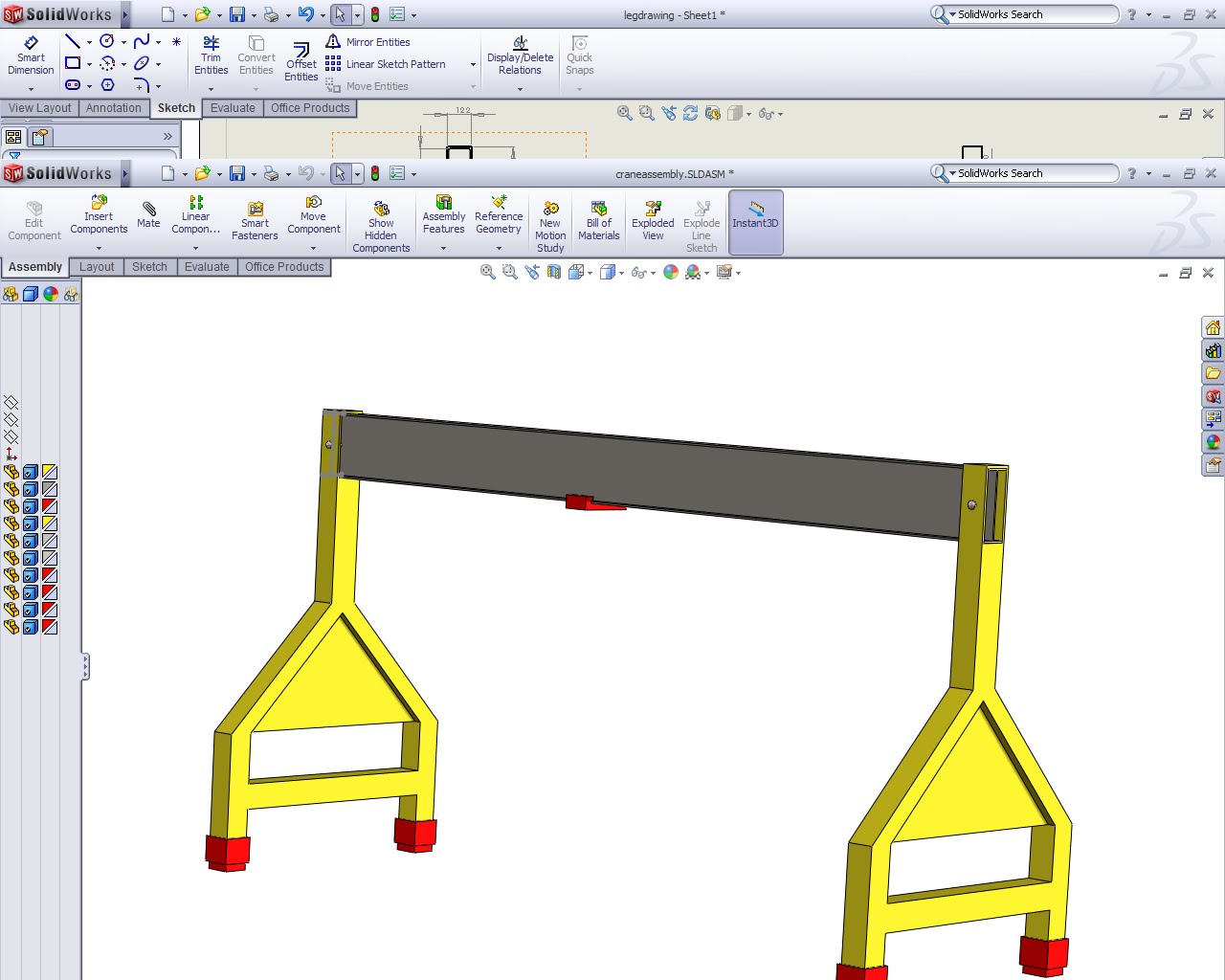
This is the updated assembly of our crane, with the changes made to the legs.

Updated Leg

This is the updated leg, with a strengthening cross member, and plate, to prevent the legs from breaking apart.
Wednesday, 21 April 2010


Tuesday, 20 April 2010


Rendered view of crane

This is the rendered view of our gantry, with typical paint colours, for identification and protection.

Model of the Pin

This is the pin used to hold the I-beam into the frame. There will be two, one on each side.
Lifting straps

A critical component is the lifting strap associated with the end product. Research has shown that a wide variety of straps and belts are available, with the overall safe working load defined by the end fitting used.
We have ralised that the product would increase its versitility if it was offered with a range of straps to suit all situatuions. Therefore the following range of products is being considered:
1. The RLL50E Ratchet Straps is endless and therefore has no end fittings. The RLL50E has a load capacity of 4000Kgf.
http://www.gtf.co.uk/component/virtuemart/category/31/cargo-straps/50mm-ratchet-straps?vmi=3
2. The RL25L Ratchet Straps have a loop sewn on each end. The RL75E has a load capacity of 5000Kgf.
http://www.gtf.co.uk/component/virtuemart/category/33/cargo-straps/75mm-cargo-straps?vmi=3
3. The RL35LD-E Ratchet Straps are an endless configuration. i.e. the webbing goes back through the buckle The RL35LD-E has a load capacitiy of 2000Kgf. The Breaking Strength is 4000Kgf. [
http://www.gtf.co.uk/component/virtuemart/category/30/cargo-straps/35mm-ratchet-straps?vmi=3
4. Sealey Lifting Strap 5 Ton Capacity 4 Metre [£57.76]
http://www.tooled-up.com/Product.asp?PID=138886
5. Sealey Lifting Strap 3 Ton Capacity 3 Metre [£30.03]
http://www.tooled-up.com/Product.asp?PID=138877
6. Draper Expert 4 Tonne 2 Metre x 120mm Lifting Strap [£21.95]
http://www.tooled-up.com/Product.asp?PID=166402
7. Endless Roundslings Brown 6Ton / 6000kgs
Endless roundslings made with 100% polyester ideal lifting slings for easy use and flexability [£8.12]
http://www.slingsandstraps.co.uk/shop/category_RSEC/Roundslings.html?shop_param=cid%3D%26
8. Endless Roundslings Grey 4Ton / 4000kgs
Endless roundslings made with 100% polyester ideal lifting slings for easy use and flexability [£5.02]
http://www.slingsandstraps.co.uk/shop/category_RSEC/Roundslings.html?shop_param=cid%3D%26
9. Endless Roundslings Yellow 3Ton / 3000kgs
Endless roundslings made with 100% polyester ideal lifting slings for easy use and flexability [£3.94]
http://www.slingsandstraps.co.uk/shop/category_RSEC/Roundslings.html?shop_param=cid%3D%26
10. Lifting Slings 2Ton / 2000Kgs Green
Duplex Lifting Slings made from polyester. 2ton capacity Colour : Green[£6.22]
http://www.slingsandstraps.co.uk/shop/category_DUPWS/Lifting-Slings-Duplex-Webbing.html?shop_param=cid%3D%26

Monday, 19 April 2010
Tender - Group M
ME2045 Solid Mechanics
Group M
Emergency Crane project
Invitation to Tender
Contents
1 Introduction
1.1 Project Goals and Objectives
1.2 Purpose of this Invitation to Tender
1.3 Form of Tenders
1.4 Procurement Timetable
2 Background
2.1 Organisation Background
2.2 Technical Environment
2.3 Current Business Systems
3 Scope and Scale of Systems
3.1 Scope
3.2 Scale
4 Key Requirements
5 General Requirements
6 Detailed Functional Requirements
7 Technical Requirements
8 Cost Information Required
9 Implementation Requirements
1 INTRODUCTION
All group’s have been invited to tender a design of a small portable crane for use in disaster relief. Whilst the majority of loose material can be removed by hand it is recognised that larger beams and objects need the use of further resources; with the difficulty of transporting larger earth moving equipment proving difficult. This is where a portable crane would prove to be most valuable. The group have established a blog that documents the progress of the design; from start to finish. It is available to view at http://emergingengineeringgroupm.blogspot.com/
1.1 Project Goals and Objectives
The key goal was to design a crane that was easily capable of lifting the required weight (1000Kg) over a distance of 4m from its initial place of rest. It also needs to be economically viable to warrant production as well as robust enough to withstand all the forces it will be subjected to.
1.2 Purpose of this Invitation to Tender
This document outlines what objectives and goals the product has been designed to meet. It has been produced so that a clear knowledge of the product can be gained from reading it.
1.3 Form of Tenders
Any response should be made to the Project Manager once a decision has been made. Email: Thomasi@aston.ac.uk
1.4 Procurement Timetable
The tendering process is due to close on Friday 23rd April 2010. A working demonstration of the equipments capability is available upon request and will also be shown in the Group Presentation on Wednesday 28th April 2010. Should the product be selected a prototype would be developed immediately.
2 BACKGROUND
2.1 Institution's Background
The group was formed upon the release of the invitation to tender (3rd March 2010). Project roles were quickly established so the design could be researched and developed; with plenty of time to identify, and rectify, any areas for improvement.
2.2 Technical Environment
The creation of the blog has allowed the group to work from a variety of different locations; often as split down sub teams. This has assisted the development of the design along with the weekly planning meetings. Situational awareness has been maintained through this weekly meeting; allowing a fresh perspective to influence any work. The use of CAD software (Solidworks) has also helped in the design and development of the product.
2.3 Current Business Systems
Each team member was allocated a role to be responsible for. Despite this, all team members have been involved in all areas of development; allowing all the group skills to be utilised.
3 SCOPE AND SCALE OF SYSTEMS
3.1 Scope
The constraints of the design were outlined in the initial invitation to tender, and are discussed in Key requirements below. This allowed a fair deal of flexibility as to the design of the crane; with a variety of alternatives considered. These alternatives are documented in the blog.
3.2 Scale
The market for the product is vast. The recent occurrence of a number of natural disasters, in a variety of locations worldwide, highlights where this design could be utilised.
4 KEY REQUIREMENTS
The project had to work to the following conditions:
Be able to lift loads of not less than 1000Kgs.
Transport the load not less than 4m from the point of lift.
Be able to be disassembled and carried manually over 100m of rough ground.
Be able to be carried by a standard Land Rover 4x4.
5 GENERAL REQUIREMENTS
In order for the design to be produced the procurement of a variety of parts, from different manufacturers is necessary. This includes a rolling hand cranked cradle, I beam section and the fabrication of the legs and shoes. In order to maximise economic savings a bulk order would be advised. Therefore production would not be agreed until all responses have been returned.
6 DETAILED FUNCTIONAL REQUIREMENTS
3.3m Long I beam section. The exact dimensions are available to view in the blog.
1000Kg Hand Pushed Trolley – Quick Fit http://www.angliahandling.co.uk/acatalog/Hand_Pushed_Trolley_-_.html
2 x Leg Supports. The exact dimensions are available to view in the blog.
4 x ‘Shoes. The exact dimensions are available to view in the blog.
4 x Bottle Jacks It was decided that the design would allow the use of generic Bottle Jacks in order to allow the use of readily available equipment. However it was recognised that a recommended bottle jack be made available with the design. This recommended bottle Jack is available at http://www.tootoo.com/d-rp1692028-hydraulic_bottle_jack/
7 TECHNICAL REQUIREMENTS
Solidworks CAD was used to design the product. All associated ‘off the shelf’ equipment has been researched and recommended to insure that it meets the strict design criteria.
8 COST INFORMATION REQUIRED
The overall cost of the design doesn’t require any training or consultancy fees to be considered. It is purely based around the cost of the equipment and fabrication of the materials used. If the design was to prove to be the winning tender then a training (how to use) manual would need to be produced to accompany the design.
9 IMPLEMENTATION REQUIREMENTS
A Gantt chart was used alongside the blog to keep a track on the product design. All group members were aware of the responsibility allocated to them and the timescale in which this duty was to be achieved. Well attended weekly group meetings allowed the discussion and solution of problems; without hindering the progress of the design.
Sunday, 18 April 2010
Meeting
As arranged a Progress meeting will be held at 1700hrs on Mon 19 April 2010. The main item to be completed is the calculation of all forces in order to select a suitable material.
Subscribe to:
Comments (Atom)